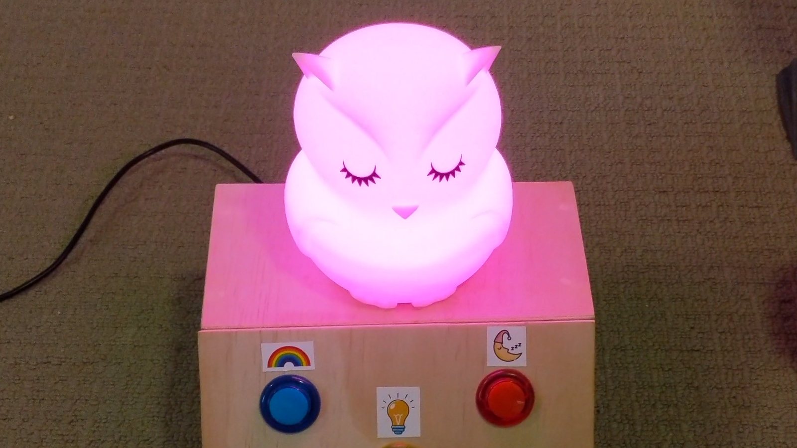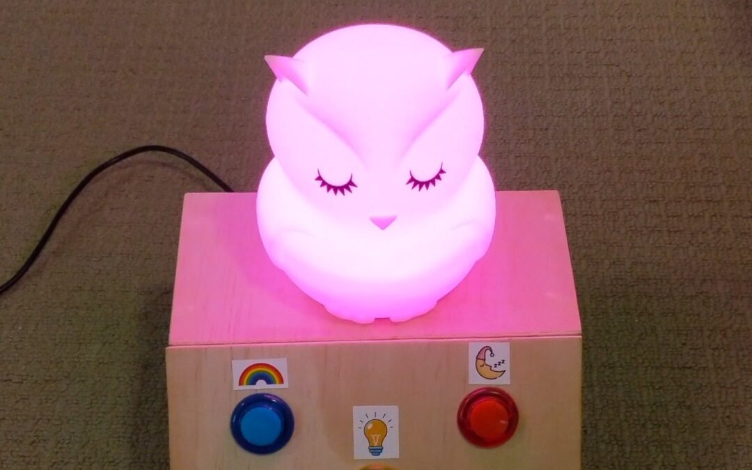
Back in late 2020 I built my daughter a night light. I could have bought one, but where’s the fun in that? I had an Arduino, a pile of jumper wires and a plan scribbled in a notebook.
The result is an owl that sits on a plywood box with three big chunky buttons and two knobs. She can pick the colour of the light by turning the knob, set it to a slow rainbow, or press the moon button and the owl fades itself to sleep over 20 minutes. Here’s what it does and how it works, circuit diagram and code included.
What does it do?
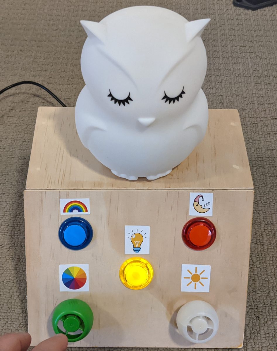
Each control has a picture sticker above it, so it’s pretty easy to work out even if you’re small and it’s dark.
- Yellow button (light bulb): on and off. When the owl is off, the yellow button glows so she can find it in the dark.
- Green knob (colour wheel): picks the colour. Turn it and the owl goes from red to green to blue and back to red again.
- White knob (sun): brightness, from barely there to full glow.
- Blue button (rainbow): rainbow mode. The owl slowly cycles through every colour on its own. In this mode the green knob changes the speed, from roughly 5 seconds per lap to nearly 2 minutes.
- Red button (sleepy moon): sleep mode. The owl jumps to full brightness in whatever colour is selected, then fades out over 20 minutes and switches itself off. The yellow button lights up again, ready for next time.
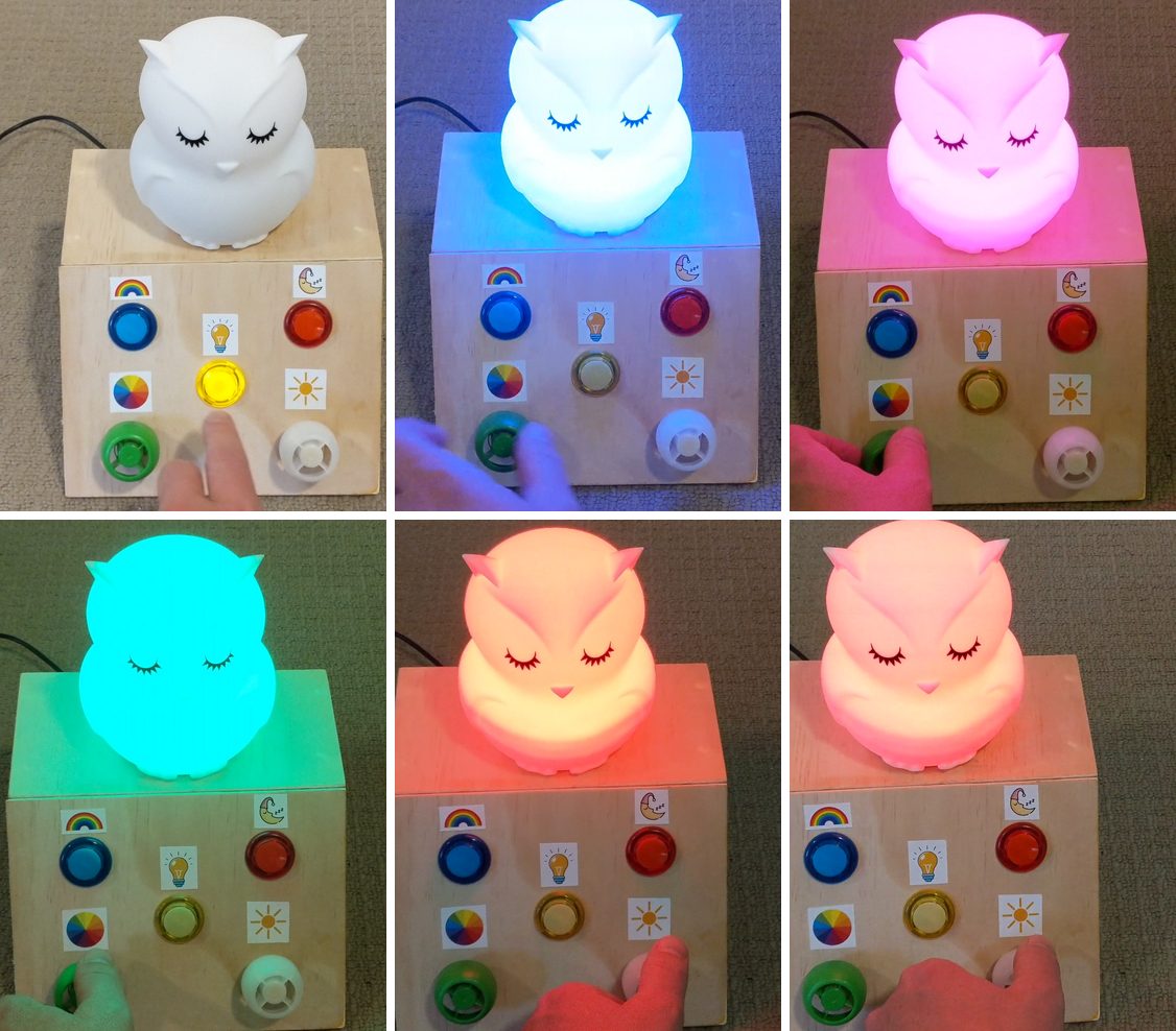
Here it is in action. I press the yellow button, then twiddle the colour knob and the brightness knob.
What’s inside the box?
The brains is a DFRobot Bluno Nano. It’s an Arduino Nano compatible board with Bluetooth built in. I didn’t use the Bluetooth at all. Maybe one day the owl gets an app. Maybe not.
The rest of the parts list is pretty short:
- DFRobot Bluno Nano (any Arduino Nano or Uno would do the job)
- 3 push buttons: yellow, blue and red, with an LED inside the yellow one
- 2 potentiometers, with recycled yoghurt lids as the knobs (upcycling at its best)
- An RGB LED inside the owl
- A 4 channel MOSFET switch module from AliExpress (IRF540N MOSFETs with optocoupler isolation) to drive the red, green and blue channels, with one channel spare
- 10k resistors for the buttons and between the Arduino and the MOSFET module, plus a 220Ω resistor for the yellow button’s LED
- A 5V supply into a terminal block
- A plywood box, a handful of stickers and heaps of jumper wires
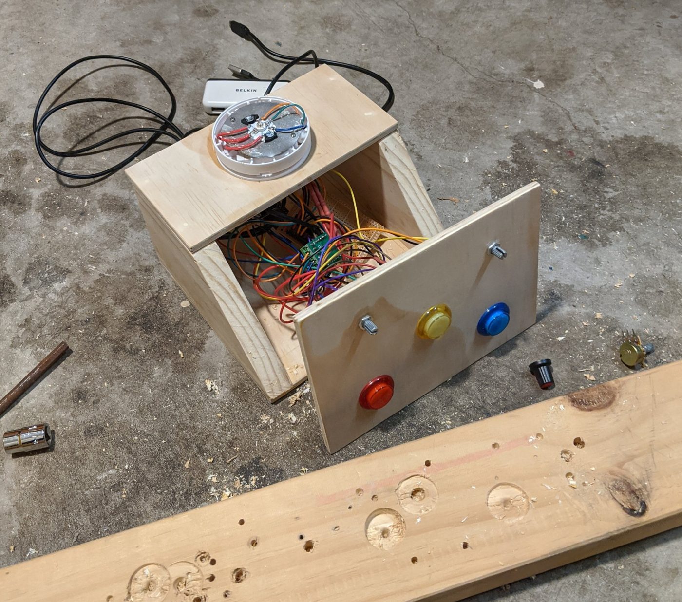
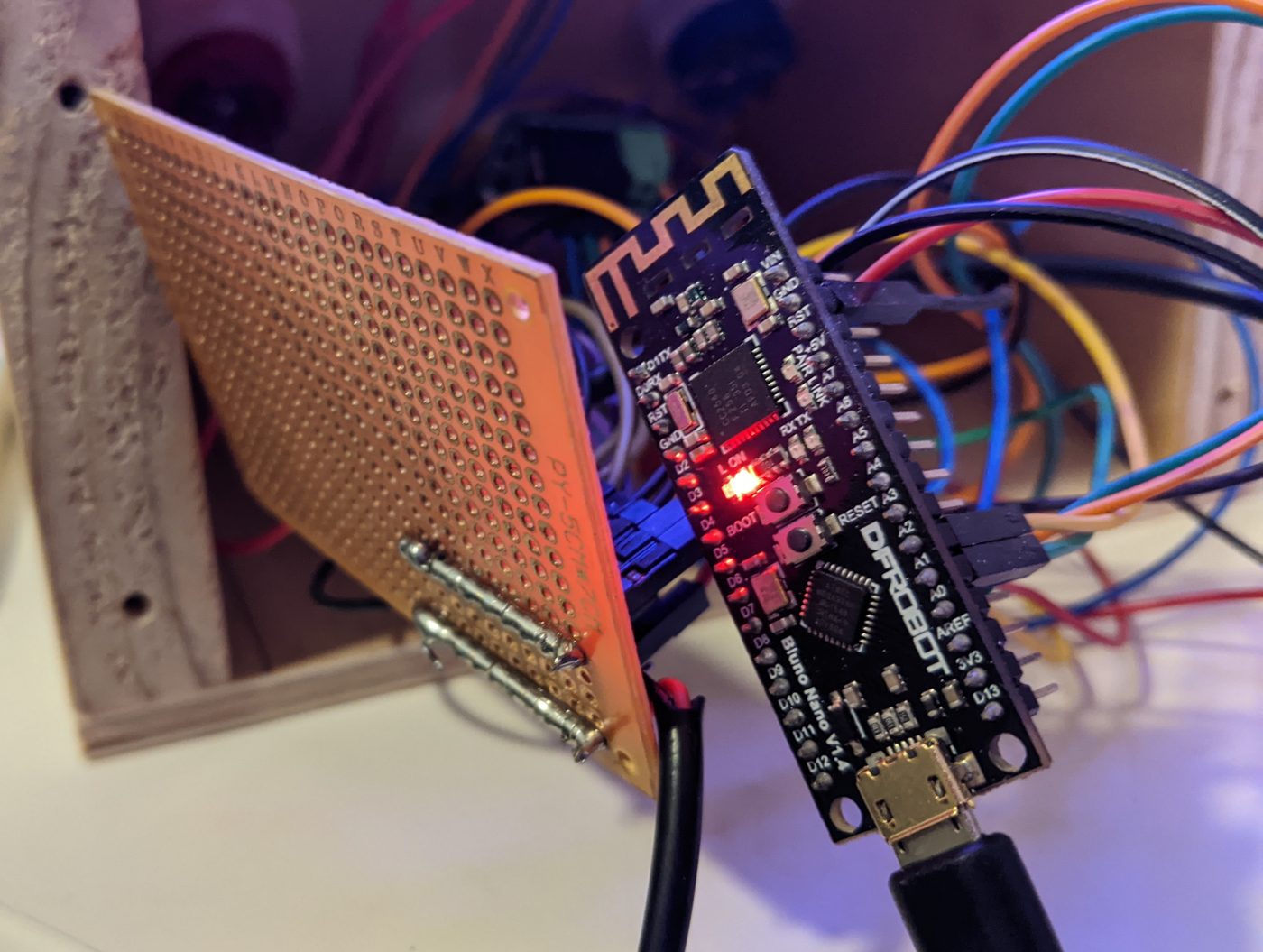
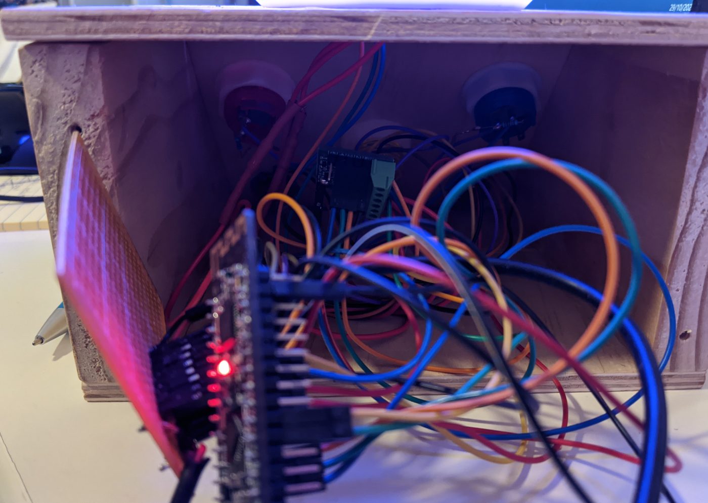
The circuit diagram
Here’s how everything is wired up. The pin numbers match the code.
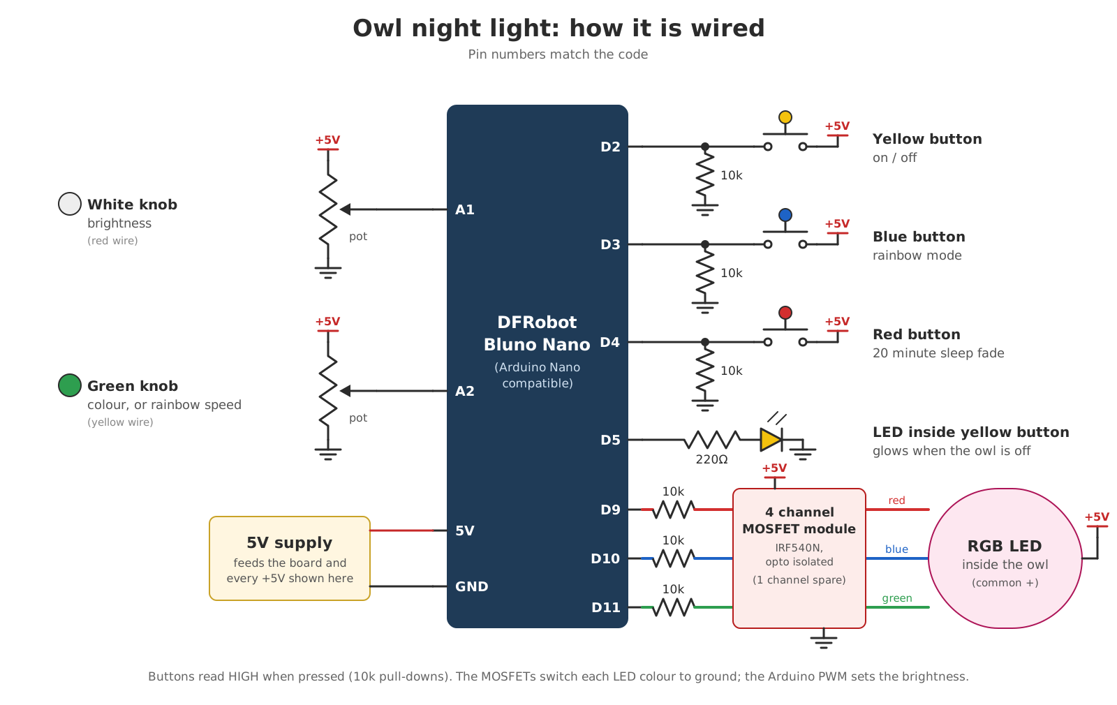
Here’s how the pieces hook up:
- Buttons go to digital pins D2 (yellow), D3 (blue) and D4 (red). One side of each button goes to 5V. The pin also has a 10k resistor down to ground, which keeps it reading LOW until the button is pressed. Pressing the button connects it to 5V and it reads HIGH.
- Knobs are potentiometers wired across 5V and ground, with the middle leg going to an analog pin. The brightness knob is on A1 and the colour knob is on A2. The Arduino reads each one as a number from 0 to 1023.
- The yellow button’s LED is on D5 through a 220Ω resistor.
- The owl’s RGB LED is controlled from D9 (red), D10 (blue) and D11 (green). Each pin goes through a 10k resistor to one input on the 4 channel MOSFET module. The LED’s common positive goes to 5V and each colour goes to one of the module’s outputs. When the Arduino turns a pin on, that MOSFET connects the colour to ground and it lights up. The Arduino pins only have to flick switches; the MOSFETs do the heavy lifting.
- Dimming comes from PWM. D9, D10 and D11 are PWM pins, which means the Arduino can turn them on and off really fast. The longer each pin spends on, the brighter that colour looks.
How does the code work?
The code is one Arduino sketch. It’s saved as nightlight7, so it’s fair to say the first few versions didn’t quite get there.
The owl is always in one of four modes: off, normal, rainbow or sleep. Every time through the main loop it reads the two knobs and three buttons, works out whether a button press should change the mode, then does whatever that mode does.
Turning a knob into a colour
The colour knob gives a number from 0 to 1023. The code splits that into thirds:
- Bottom third: red fades out while green fades in
- Middle third: green fades out while blue fades in
- Top third: blue fades out while red fades in
So turning the knob all the way walks you around the colour wheel and back to where you started. Brightness is then easy; each colour value gets multiplied by the brightness knob’s position.
Rainbow mode
Rainbow mode uses the same colour wheel code, but instead of reading the colour from the knob it steps a counter from 0 to 1023 and starts again. The colour knob sets how long it waits between steps, anywhere from about 5 to 105 milliseconds. Over 1,023 steps that works out to roughly 5 seconds per lap at the fast end and close to 2 minutes at the slow end.
Sleep mode
Sleep mode starts at full brightness and drops one step every 4.7 seconds. There are 255 steps, and 255 × 4.7 seconds is about 20 minutes. When it gets to the bottom it switches the owl off and turns the yellow button light back on.
My notebook says 30 minutes. The code still has the 30 minute value in it, commented out. Somewhere along the way 20 minutes won.
Making it kid proof
After any button press the code ignores the buttons for half a second. That stops one enthusiastic press being read as five. Pressing yellow while the owl is in rainbow or sleep mode takes it back to normal mode rather than off, so a stray press doesn’t plunge the room into darkness.
If you like this sort of dad project, I also built a playing time calculator for kids’ sport.
The full code
Here’s the whole sketch if you want to build your own. My project file is set up for an Arduino Uno, and it doesn’t use any libraries, so it should run on a Nano or an Uno as is.
Show the Arduino code (nightlight7.ino)
int red = 9; //red LED
int blue = 10;  //blue LED
int green = 11;  // the PWM pin the green LED is attached to
float maxbrightness = 255;
float brightness =0;
int buttoninterval = 500;
float millisinterval = 15;
unsigned long previousbuttonMillis = 0;
unsigned long previousMillis = 0;

const int yellowbutton = 2;     // the number of the pushbutton pin
const int bluebutton = 3;
const int redbutton = 4;
const int yellowbuttonled = 5;

int redVal = 0;   // Variables to store the values to send to the pins
int grnVal = 0;
int bluVal = 0;
int potVal = 0; // Variable to store the input from the potentiometer

int yellowbuttonstate = 0;
int redbuttonstate = 0;
int bluebuttonstate = 0;

int mode = 0;
int disablebutton=0;

void setup() {

  pinMode(red, OUTPUT);
  pinMode(blue, OUTPUT);
  pinMode(green, OUTPUT);
  pinMode(yellowbuttonled, OUTPUT);
  randomSeed(analogRead(0));

  //Serial.begin(9600);
  analogWrite(yellowbuttonled, 255); // turn on yellow button LED

}

void get_colour(int potVal) //give it a number 1-1023 and it will return 3 colours - RGB
{
  if (potVal < 341)  // Lowest third of the potentiometer's range (0-340)
  {
    potVal = (potVal * 3) / 4; // Normalize to 0-255

    redVal = 256 - potVal;  // Red from full to off
    grnVal = potVal;        // Green from off to full
    bluVal = 1;             // Blue off
  }
  else if (potVal < 682) // Middle third of potentiometer's range (341-681)
  {
    potVal = ( (potVal-341) * 3) / 4; // Normalize to 0-255

    redVal = 1;            // Red off
    grnVal = 256 - potVal; // Green from full to off
    bluVal = potVal;       // Blue from off to full
  }
  else  // Upper third of potentiometer"s range (682-1023)
  {
    potVal = ( (potVal-683) * 3) / 4; // Normalize to 0-255

    redVal = potVal;       // Red from off to full
    grnVal = 1;            // Green off
    bluVal = 256 - potVal; // Blue from full to off
  }
}

void loop() {

  unsigned long currentMillis = millis();
  unsigned long currentbuttonMillis = millis();

  //read knobs
  float dimmingknob = analogRead(A1); // red knob
  float colourknob = analogRead(A2); // yellow knob

  //read buttons
  redbuttonstate = digitalRead(redbutton);
  yellowbuttonstate = digitalRead(yellowbutton); // on off button
  bluebuttonstate = digitalRead(bluebutton);

  //Serial.println("Red");
  //Serial.println(redbuttonstate);
  //Serial.println("Yellow");
  //Serial.println(yellowbuttonstate);
  //Serial.println("Blue");
  //Serial.println(bluebuttonstate);

  if (currentbuttonMillis - previousbuttonMillis >= buttoninterval)
    {disablebutton=0;}

  if ((yellowbuttonstate == HIGH)&&(disablebutton==0)&&((mode==0)||(mode==2)||(mode==3)))
    {
      mode=1;
      analogWrite(yellowbuttonled, 0); // turn off yellow button LED
      disablebutton=1; //put timer on to stop reading button
      previousbuttonMillis =millis();
    }

  if ((yellowbuttonstate == HIGH)&&(disablebutton==0)&&(mode==1))
    {
      mode=0;
      analogWrite(yellowbuttonled, 255); // turn on yellow button LED
      analogWrite(red, 0);   // Turn off leds
      analogWrite(green, 0);
      analogWrite(blue, 0);
      disablebutton=1; //put timer on to stop reading button
      previousbuttonMillis =millis();
    }

  if ((bluebuttonstate == HIGH)&&(disablebutton==0))
    {
      analogWrite(yellowbuttonled, 0); // turn off yellow button LED
      disablebutton=1; //put timer on to stop reading button
      previousbuttonMillis =millis();
      mode=2;
      potVal=0;
    }

  if ((redbuttonstate == HIGH)&&(disablebutton==0))
    {
      analogWrite(yellowbuttonled, 0); // turn off yellow button LED
      disablebutton=1; //put timer on to stop reading button
      previousbuttonMillis =millis();
      mode=3;
      brightness=255;

    }

  if (mode==0) // Off
  {

    delay(5);

  }
  else if (mode==1) // normal mode - colour changing and dimming with knobs
  {
    brightness = ((dimmingknob/1024)*(maxbrightness/255));
    //Serial.println("brightness");
    //Serial.println(brightness);
    //analogWrite(red, random(10, 255));
    // analogWrite(blue, random(10, 255));
    //analogWrite(green, random(10, 255));

    //Serial.println("Dimming");
    //Serial.println(dimmingknob);
    //Serial.println("Colour");
    //Serial.println(colourknob);

    potVal=colourknob;

    get_colour(potVal);

    analogWrite(red, (redVal*brightness));   // Write values to LED pins
    analogWrite(green, (grnVal*brightness));
    analogWrite(blue, (bluVal*brightness));

  }

  else if (mode==2) // blue button - first press - rainbow cycle
  {

    brightness = ((dimmingknob/1024)*(maxbrightness/255));
    millisinterval = ((colourknob/1024)*100)+5;
    //Serial.println("Millis");
   // Serial.println(millisinterval);

    get_colour(potVal);
    analogWrite(red, (redVal*brightness));   // Write values to LED pins
    analogWrite(green, (grnVal*brightness));
    analogWrite(blue, (bluVal*brightness));

    if (currentMillis - previousMillis >= millisinterval)
    {
      potVal=potVal+1;

      previousMillis =millis();
    }
    if (potVal>1022){potVal=0;}
    //Serial.println(potVal);
  }

  else if (mode==3) // Sleep mode - Dim to off over the next 20 mins - red button pressed
  {

    potVal=colourknob;
    get_colour(potVal);

    analogWrite(red, (redVal*brightness/255));   // Write values to LED pins
    analogWrite(green, (grnVal*brightness/255));
    analogWrite(blue, (bluVal*brightness/255));

    //millisinterval=200; //test
    //millisinterval=7058; // 30 min dim time
    millisinterval=4705; // 20 min dim time = 20min x 60 x 1000 /255

    if (currentMillis - previousMillis >= millisinterval)
    {
      brightness=brightness-1;
      previousMillis =millis();
    }

    if(brightness<2)
    {
      brightness=0;
      mode=0;
      analogWrite(yellowbuttonled, 255); // turn on yellow button LED
      analogWrite(red, 0);   // Turn off leds
      analogWrite(green, 0);
      analogWrite(blue, 0);
    }

  }

  //delay(500); //not sure if this is needed

} // end of loop
If you build one, I’d love to see it.