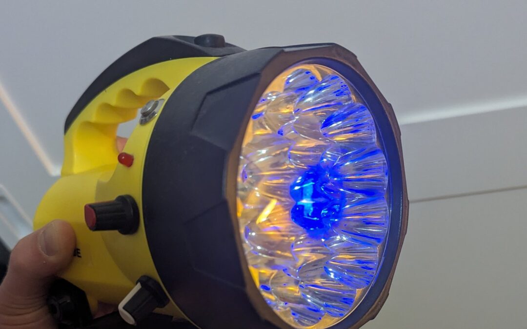
I’ve already written about the Arduino owl night light I built for one of my daughters. Her sister got a torch. Not just any torch, though. A torch that does colours.
So in October 2024 I picked up an old yellow lantern torch from a charity shop, pulled its guts out and put an Arduino in it. It runs on a rechargeable battery, has a knob for colour, a knob for brightness and a button that turns on a rainbow mode. Here’s what it does and how it works, circuit diagram and code included.
What does it do?
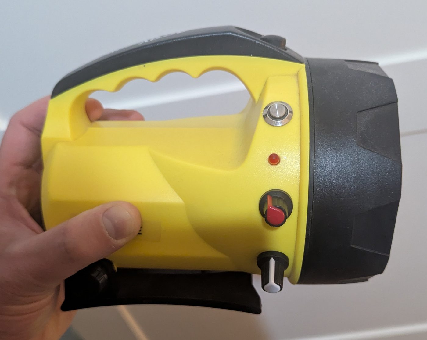
The controls are all on the side of the torch:
- Black button on top of the handle: the main power switch.
- Silver button: changes mode. Each press goes from on, to rainbow, to off, then back to on. When you first switch the torch on it starts in normal mode.
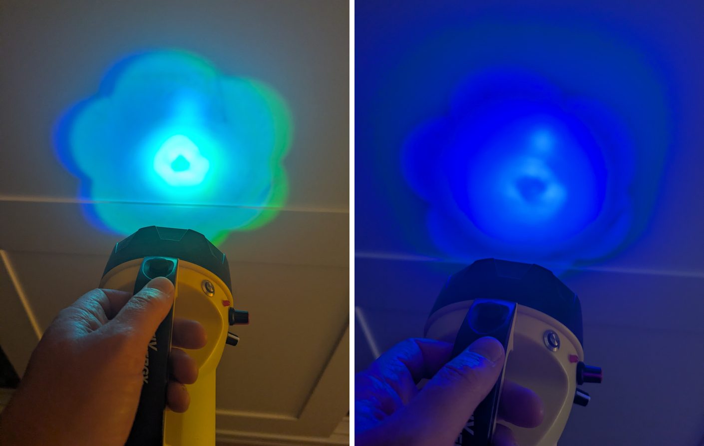
- Red knob: picks the colour. Turn it and the beam goes from red to green to blue and back towards red. Turn it right to the end and it goes white.
- White knob: brightness.
- Small red LED: a low battery warning, there to flash when the battery drops below 15%.
In rainbow mode the torch cycles through every colour on its own, and the red knob changes how fast it goes. At the quick end it does a full lap in about 5 seconds. At the slow end it takes close to 2 minutes.
What’s inside?
The brains is a SparkFun Qduino Mini. It’s a small Arduino compatible board that runs at 3.3V, and the best bit for a torch is that it has a LiPo battery charger and a battery fuel gauge built in. That means no separate charging board, and the code can ask the battery how full it is.
The parts list is pretty short:
- SparkFun Qduino Mini
- 3.7V 1100mAh LiPo battery
- 3W RGB LED on a heat sink
- 3 N-channel MOSFETs (60V 30A), one for each colour
- 2 potentiometers for the knobs
- 1 silver push button for the modes
- A small red LED and a 220Ω resistor for the low battery warning
- 10k resistors for the button and the MOSFETs
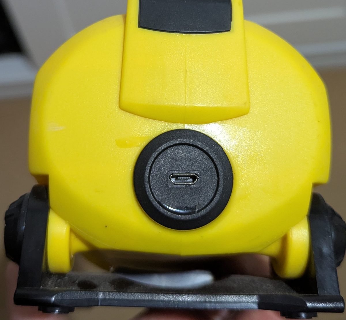
- A micro USB port on the back of the torch for charging
- One yellow lantern torch from a charity shop
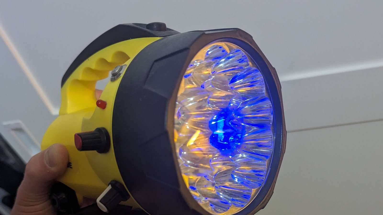
I took out the original LEDs and fitted the 3W RGB LED and its heat sink in the middle of the old reflector.
The build
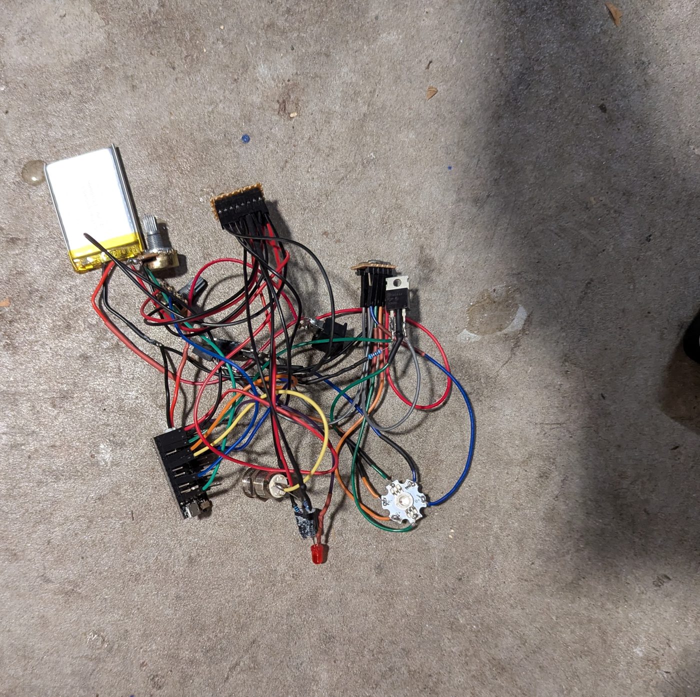
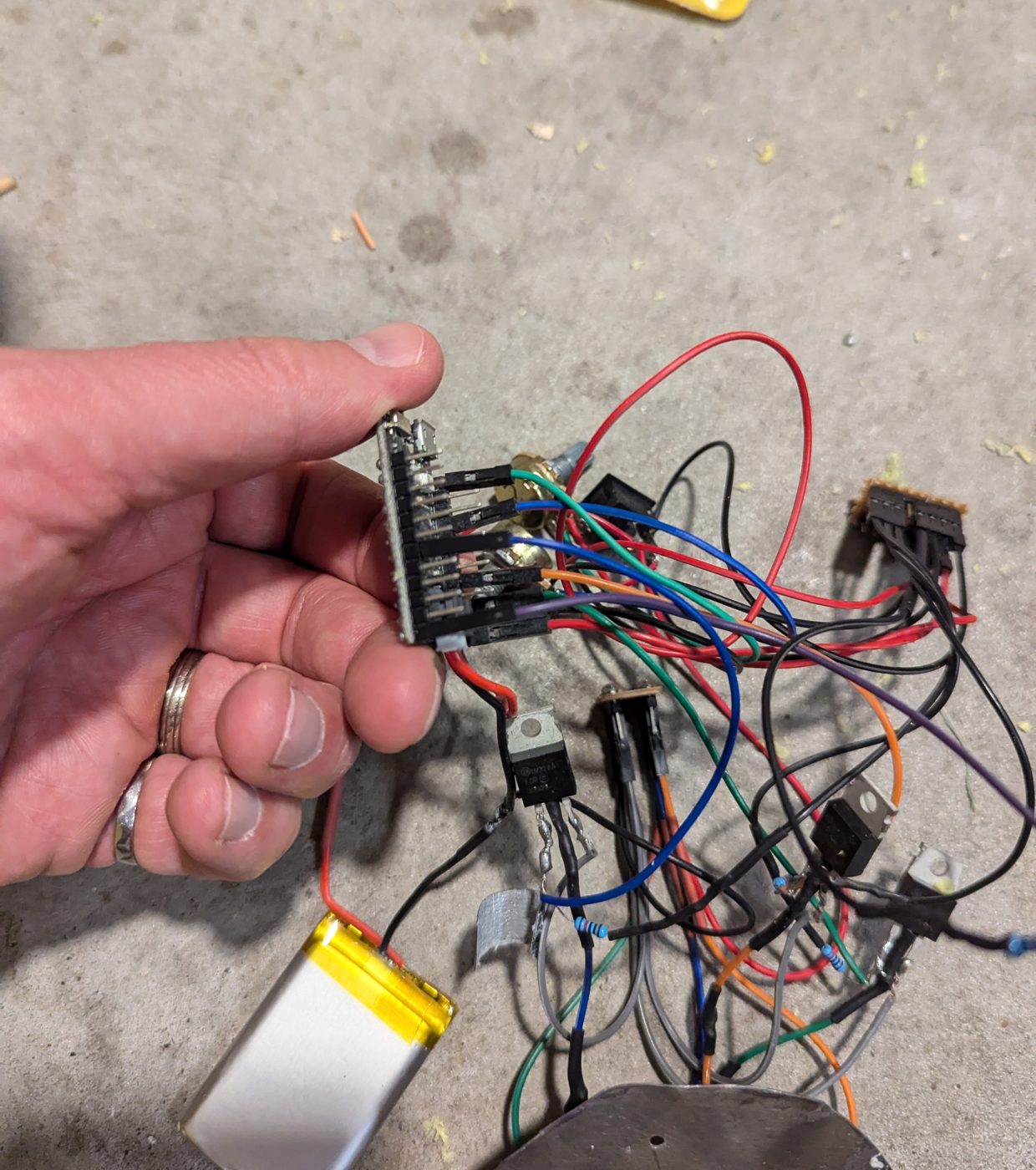
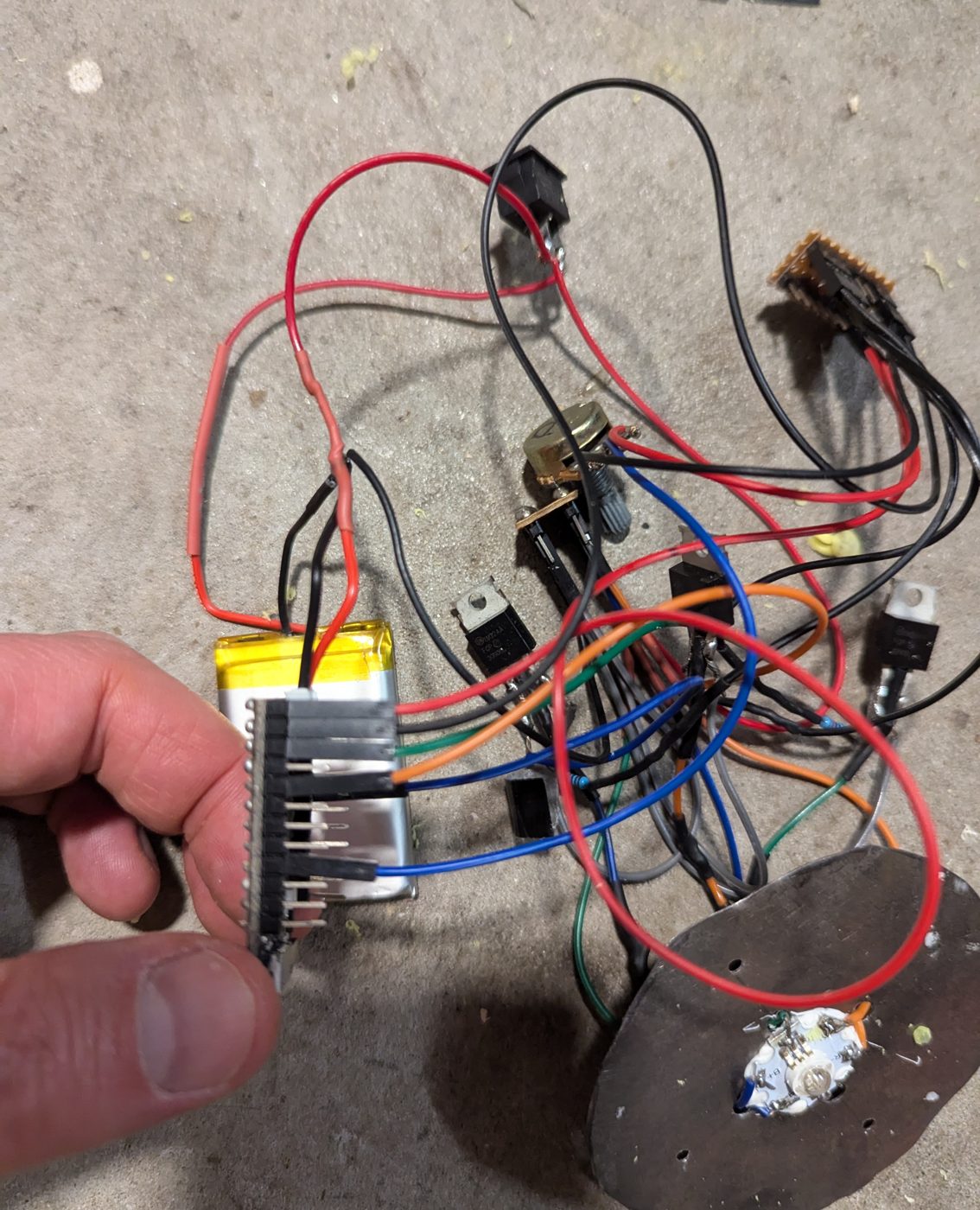
It started as a pile of parts and wires on the garage floor.
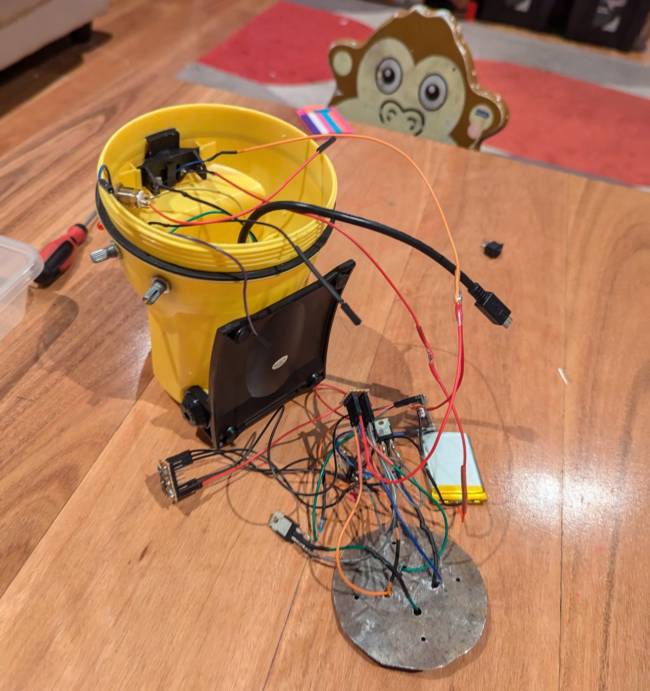
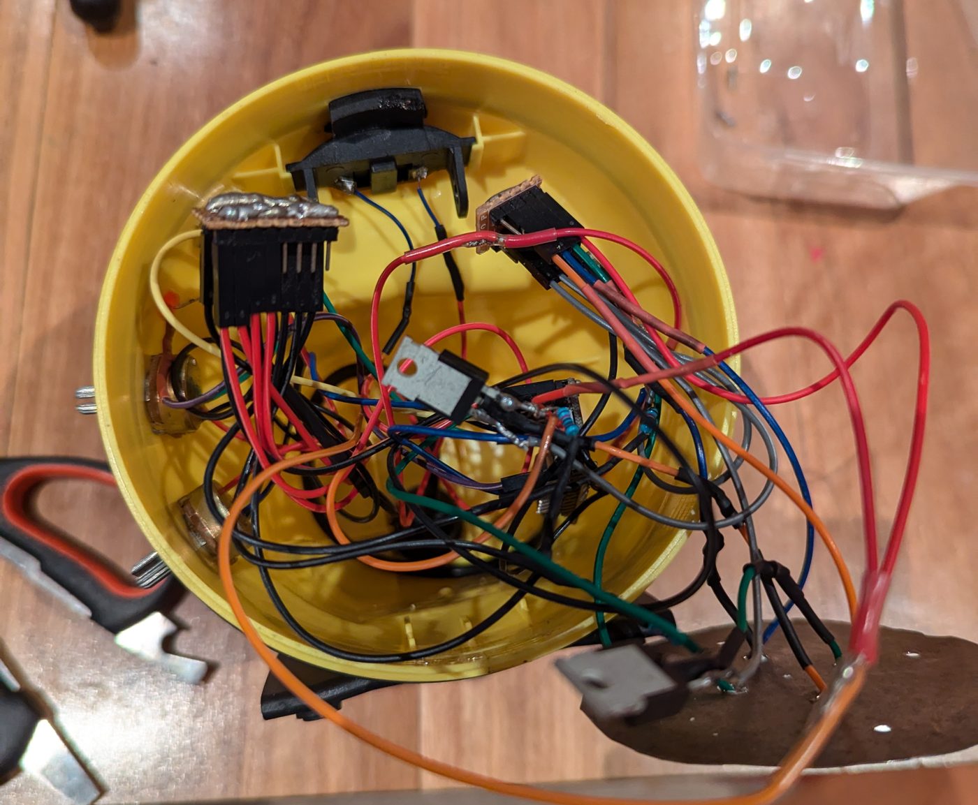
The circuit diagram
Here’s how everything is wired up. The pin numbers match the code.
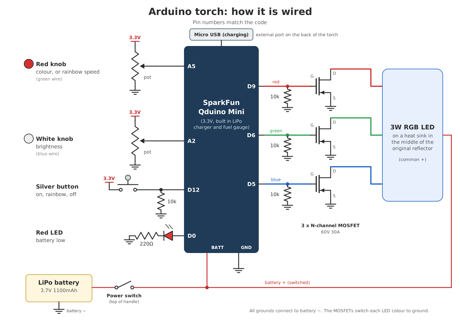
Here’s how the pieces hook up:
- Power: the LiPo battery goes through the power switch on top of the handle. After the switch it feeds both the Qduino Mini and the positive side of the LED. The micro USB port on the back charges the battery through the Qduino’s built in charger.
- Knobs are potentiometers wired across 3.3V and ground. The colour knob is on A5 and the brightness knob is on A2. The Arduino reads each one as a number from 0 to 1023.
- The silver button goes to D12, with a 10k resistor down to ground. The pin reads LOW until the button is pressed, then the button connects it to 3.3V and it reads HIGH.
- The low battery LED is on D0 through a 220Ω resistor.
- The 3W RGB LED is driven from D9 (red), D6 (green) and D5 (blue). Each pin goes to the gate of its own MOSFET, with a 10k resistor from the gate to ground so it stays off while the Arduino starts up. The LED’s common positive goes to the battery, and each MOSFET connects one colour to ground when the Arduino turns it on.
- Dimming comes from PWM. D9, D6 and D5 are PWM pins, which means the Arduino can turn them on and off really fast. The longer each pin spends on, the brighter that colour looks.
How does the code work?
The sketch is called LEDtorchv6, so it took a few goes. The colour wheel, rainbow mode and button handling all came straight from the owl night light.
The torch is always in one of three modes: on, rainbow or off. Every time through the main loop it reads the two knobs and the button, changes mode if the button was pressed, then does whatever that mode does.
Turning a knob into a colour
The colour knob gives a number from 0 to 1023. Like the night light, the code splits that into thirds:
- Bottom third: red fades out while green fades in
- Middle third: green fades out while blue fades in
- Top third: blue fades out while red fades in
The torch has one extra trick. From 1000 up to the end of the knob it turns all three colours on at full, which gives white. Sometimes you just need a normal torch.
Brightness
Each colour value gets multiplied by the brightness knob’s position. The code also caps the maximum at 200 out of 255, or about 78% of full power. At 100% it was too bright, and the LED got hot.
Rainbow mode
Rainbow mode uses the same colour wheel, but steps a counter from 0 to 1023 and starts again. The red knob sets the wait between steps, anywhere from about 5 to 105 milliseconds. Over 1,023 steps that works out to roughly 5 seconds per lap at the fast end and close to 2 minutes at the slow end. Because the white section is part of the wheel, each lap ends with a quick flash of white.
Keeping an eye on the battery
Once a minute the code asks the Qduino’s fuel gauge how much charge is left. Below 15%, the red LED on the side flashes on and off every half second.
Making it kid proof
Like the night light, the code ignores the button for half a second after each press. That stops one enthusiastic press being read as three.
If you like this sort of dad project, check out the owl night light or the playing time calculator for kids’ sport.
The full code
Here’s the whole sketch if you want to build your own. It uses the Qduino library for the fuel gauge, so you’ll need to install that in the Arduino IDE first.
Show the Arduino code (LEDtorchv6.ino)
#include "Arduino.h"
#include "Wire.h"
#include "Qduino.h"

fuelGauge battery;  // initialize the library
qduino q;

int battlow_led = 0; //battery low indicator LED
int torchbuttonstate = 0;

int red = 9; //red LED
int blue = 5;  //blue LED
int green = 6;  // the PWM pin the green LED is attached to

int redVal = 0;   // Variables to store the values to send to the pins
int grnVal = 0;
int bluVal = 0;
int potVal = 0; // Variable to store the input from the potentiometer

int mode = 1;
int disablebutton=0;
int buttoninterval = 500;
float millisinterval = 15;
int battery_flash_mode=0;
int batt_charge = 100;

float maxbrightness = 200;
float brightness =0;

unsigned long previousbuttonMillis = 0;
unsigned long previousMillis = 0;
unsigned long batteryflashMillis = 0;
unsigned long batterycheckMillis = 0;

const int torchbutton = 12;

void setup()
{

  Wire.begin();

  //Serial.begin(9600);  // start Serial port
  battery.setup();  // setup fuel gauge
  q.setup();

  //while(!Serial);  // wait for Serial port to be opened

  pinMode(battlow_led, OUTPUT);

  pinMode(red, OUTPUT);
  pinMode(blue, OUTPUT);
  pinMode(green, OUTPUT);

  //Serial.println("Begin");
}

void get_colour_old(int potVal) //give it a number 1-1023 and it will return 3 colours - RGB
{
  if (potVal < 341)  // Lowest third of the potentiometer's range (0-340)
  {
    potVal = (potVal * 3) / 4; // Normalize to 0-255

    redVal = 256 - potVal;  // Red from full to off
    grnVal = potVal;        // Green from off to full
    bluVal = 1;             // Blue off
  }
  else if (potVal < 682) // Middle third of potentiometer's range (341-681)
  {
    potVal = ( (potVal-341) * 3) / 4; // Normalize to 0-255

    redVal = 1;            // Red off
    grnVal = 256 - potVal; // Green from full to off
    bluVal = potVal;       // Blue from off to full
  }
  else  // Upper third of potentiometer"s range (682-1023)
  {
    potVal = ( (potVal-683) * 3) / 4; // Normalize to 0-255

    redVal = potVal;       // Red from off to full
    grnVal = 1;            // Green off
    bluVal = 256 - potVal; // Blue from full to off
  }
}

void get_colour(int potVal) //give it a number 1-1023 and it will return 3 colours - RGB
{
  if (potVal < 341)  // Lowest third of the potentiometer's range (0-340)
  {
    potVal = (potVal * 3) / 4; // Normalize to 0-255

    redVal = 256 - potVal;  // Red from full to off
    grnVal = potVal;        // Green from off to full
    bluVal = 1;             // Blue off
  }
  else if (potVal < 682) // Middle third of potentiometer's range (341-681)
  {
    potVal = ( (potVal-341) * 3) / 4; // Normalize to 0-255

    redVal = 1;            // Red off
    grnVal = 256 - potVal; // Green from full to off
    bluVal = potVal;       // Blue from off to full
  }
  else  if (potVal < 1000) // Upper third of potentiometer"s range (682-1020)
  {
    potVal = ( (potVal-683) * 3) / 4; // Normalize to 0-255

    redVal = potVal;       // Red from off to full
    grnVal = 1;            // Green off
    bluVal = 256 - potVal; // Blue from full to off
  }
  else
  {
    redVal = 255;            // Make white at the very end
    grnVal = 255;
    bluVal = 255;
  }
}

void loop()
{

  unsigned long currentMillis = millis();
  unsigned long currentbuttonMillis = millis();

  //read buttons
  torchbuttonstate = digitalRead(torchbutton);

  //mode=1;

  //read knobs
  float dimmingknob = analogRead(A2); // green wire
  float colourknob = analogRead(A5); // bue wire
  //int charge = battery.chargePercentage();  // get %
  //battery.reset();  // reset for next data request

  if (currentbuttonMillis - previousbuttonMillis >= buttoninterval)
    {disablebutton=0;}

  if ((torchbuttonstate == HIGH)&&(disablebutton==0))
    {

      disablebutton=1; //put timer on to stop reading button
      previousbuttonMillis =millis();

      mode=mode +1;
      if (mode==3){mode=0;}
      potVal=0;
    }

   if (mode==0) // Off
  {

    delay(5);
    analogWrite(red, 0);
    analogWrite(blue, 0);
    analogWrite(green, 0);

  }
  else if (mode==1) // normal mode - colour changing and dimming with knobs
  {
    brightness = ((dimmingknob/1024)*(maxbrightness/255));
    //Serial.println("brightness");
    //Serial.println(brightness);
    //analogWrite(red, random(10, 255));
    // analogWrite(blue, random(10, 255));
    //analogWrite(green, random(10, 255));

    //Serial.println("Dimming");
    //Serial.println(dimmingknob);
    //Serial.println("Colour");
    //Serial.println(colourknob);

    potVal=colourknob;

    get_colour(potVal);

    analogWrite(red, (redVal*brightness));   // Write values to LED pins
    analogWrite(green, (grnVal*brightness));
    analogWrite(blue, (bluVal*brightness));

  }
  else if (mode==2) //  button - first press - rainbow cycle
  {

    brightness = ((dimmingknob/1024)*(maxbrightness/255));
    millisinterval = ((colourknob/1024)*100)+5;
    //Serial.println("Millis");
   // Serial.println(millisinterval);

    get_colour(potVal);
    analogWrite(red, (redVal*brightness));   // Write values to LED pins
    analogWrite(green, (grnVal*brightness));
    analogWrite(blue, (bluVal*brightness));

    if (currentMillis - previousMillis >= millisinterval)
    {
      potVal=potVal+1;

      previousMillis =millis();
    }
    if (potVal>1022){potVal=0;}
    //Serial.println(potVal);
  }

  //check battery status and if low, flash LED
  //check battery every minute
  if (currentMillis - batterycheckMillis > 60000 )
  {
    batt_charge = battery.chargePercentage();
    battery.reset();
    //Serial.println("Batt charge: ");
    //Serial.println(batt_charge);
    batterycheckMillis =millis();

  }

  if (batt_charge <= 15)
  {
    if (currentMillis - batteryflashMillis >= 500)
    {
      if (battery_flash_mode == 0)
      {
        digitalWrite(battlow_led, HIGH);
        battery_flash_mode =1;
      }
      else
      {
        digitalWrite(battlow_led, LOW);
        battery_flash_mode =0;
      }
      batteryflashMillis =millis();
    }
  }

  delay(10);  // wait a second to read again
}
If you build one, I’d love to see it.